# Arduboy homemade package
Arduino IDE board package for Arduboy and homemade versions with the following advantages:
* Single install
* Includes all Arduboy libraries with support for alternate displays and wiring
* Includes Arduboy optimized Arduino core with extra features and space savings
* Cathy3K bootloader support
#### To install the package:
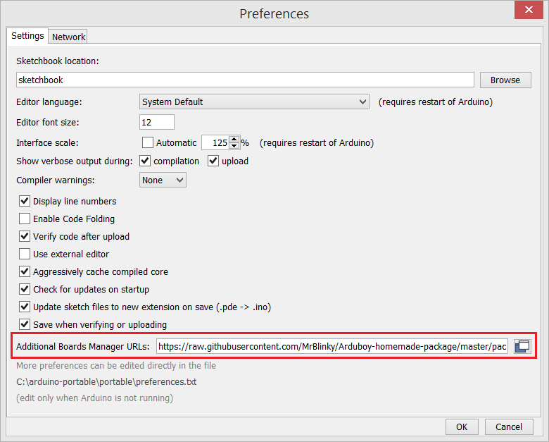
* Start Arduino IDE and press **CTRL + comma** to select properties.
* Copy and paste the URL below in **Additional Boards Manager URLs:** text box and click on **OK**
```
https://raw.githubusercontent.com/MrBlinky/Arduboy-homemade-package/master/package_arduboy_homemade_index.json
```

After this:
* Go to **Tools > Boards > Board manager**
* In the text box type **homemade** or **Arduboy homemade**
* Click on the **Arduboy Homemade package** and click the **Install** button.
You can now select **Arduboy, Arduboy DevKit** and **Homemade Arduboy boards** from the Tools menu.

## Libraries
This package contains all the currently available Arduboy libraries with changes for homemade Arduboys. If Arduboy libraries were installed manually, it is recommended to uninstall them.
## Pin wiring table
| Arduboy function | Arduboy
Leonardo/Micro | DevelopmentKit | ProMicro 5V
(standard wiring) | ProMicro 5V
(alternate wiring) |
| ---------------- | ---------------------- | ----------- | ---------------------------------- | --------------------------------- |
| OLED CS | 12 PORTD6 | 6 PORTD7 | GND | 1/TXO PORTD3* |
| OLED DC | 4 PORTD4 | 4 PORTD4 | 4 PORTD4 | 4 PORTD4 |
| OLED RST | 6 PORTD7 | 12 PORTD6 | 6 PORTD7 | 2 PORTD1* |
| SPI SCK | 15 PORTB1 | 15 PORTB1 | PORTB 1 | PORTB1 |
| SPI MOSI | 16 PORTB2 | 16 PORTB2 | PORTB2 | PORTB2 |
| RGB LED RED | 10 PORTB6 | _ | 10 PORTB6 | 10 PORTB6 |
| RGB LED GREEN | 11 PORTB7 | _ | - | 3 PORTD0* |
| RGB LED BLUE | 9 PORTB5 | 17 PORTB0 | 9 PORTB5 | 9 PORTB5 |
| RxLED | PORTB0 | _ | PORTB0 | PORTB0 |
| TxLED | PORTD5 | _ | PORTD5 | PORTD5 |
| BUTTON UP | A0 PORTF7 | 8 PORTB4 | A0 PORTF7 | A0 PORTF7 |
| BUTTON RIGHT | A1 PORTF6 | 5 PORTC6 | A1 PORTF6 | A1 PORTF6 |
| BUTTON LEFT | A2 PORTF5 | 9 PORTB5 | A2 PORTF5 | A2 PORTF5 |
| BUTTON DOWN | A3 PORTF4 | 10 PORTB6 | A3 PORTF4 | A3 PORTF4 |
| BUTTON A (left) | 7 PORTE6 | A0 PORTF7 | 7 PORTE6 | 7 PORTE6 |
| BUTTON B (right) | 8 PORTB4 | A1 PORTF6 | 8 PORTB4 | 8 PORTB4 |
| SPEAKER PIN 1 | 5 PORTC6 | A2 PORTF5 | 5 PORTC6 | 5 PORTC6 |
| SPEAKER PIN 2 | 13 PORTC7 | A3 PORTF4** | GND | 6 PORTD7* |
|----------------- | ---------------------- | ----------- | ---------------------------------- | --------------------------------- |
| CARD_CS | 0 PORTD2*** | - | - | 0 PORTD2*** |
| SPI MISO | 14 PORTB3*** | - | - | 14 PORTB3*** |
Numbers before the portnames are Arduino assigned pin numbers.
(*)
Pro Micro alternate wiring pins:
* PORTD3 OLED CS
* PORTD1 OLED RST
* PORTD7 SPEAKER 2
* PORTD0 RGB LED GREEN
(**)
speaker pin 2 output is connected to speaker pin 1 on DevKit hardware. To
prevent the IO pins from possible damage, speaker pin 2 should *NOT* be
configured as an output.
(***)
Future Flash cart support:
* 0 PORTD2 Future flash cart chip select
* 14 PORTB3 flash cart data in (MISO)